SF6O2 Etching
#include <psSF6O2Etching.hpp>
GPU and CPU compatible
The model for SF6O2 etching of silicon is based on a model by Belen et al. 1 and summarized here. For implementation details refer to here. To describe the feature scale simulation of SF6O2 plasma etching, the surface rates of both ions and neutral particles, specifically fluorine and oxygen, and the surface coverages of neutrals, are considered. Ray tracing is used for the calculation of the surface rates, which are used for calculating coverages during each time step. The etch rate is determined the three physical phenomena:
- Chemical etching
- Physical sputtering
- Ion-enhanced etching
In the process of chemical etching, the fluorine from the SF6 species reacts with the exposed silicon surface. Physical sputtering is caused by high-energy ions impacting the surface. Due to an applied bias, ions strike the wafer surface with a high enough kinetic energy, $E_{ion} > E_{th}$ to break the existing bonds in the silicon wafer or other exposed materials. Lastly, ion-enhanced etching, also known as reactive ion etching (RIE), combines the two previous effects. Since silicon surfaces that are saturated with fluorine are more prone to physical sputtering, the threshold energy for releasing the silicon atom $E_{th}$ is significantly reduced compared to non-fluorinated surfaces. Therefore, ion-enhanced etching provides an etch rate that is larger than the sum of the chemical etching and sputtering.
The surface can be covered in fluorine or oxygen. The physical model keeps track of these coverages, given by $\theta_F$ and $\theta_O$, respectively, by calculating the flux-induced rates and considering the coverages from the previous time step. They are calculated with Langmuir–Hinshelwood-type surface site balance equations, given by:
\begin{equation} \sigma_{Si}\cfrac{d\theta_{F}}{dt}=\beta_{F}\Gamma_{F}\left(1-\theta_{F}-\theta_{O}\right)-k\sigma_{Si}\theta_{F}-2Y_{ie}\Gamma_{i}\theta_{F} \label{equ:thetaF} \end{equation}
\begin{equation} \sigma_{Si}\cfrac{d\theta_{O}}{dt}=\beta_{O}\Gamma_{O}\left(1-\theta_{F}-\theta_{O}\right)-\beta\sigma_{Si}\theta_{O}-Y_{O}\Gamma_{i}\theta_{O} \label{equ:thetaO} \end{equation}
The term $\sigma_{Si}$ represents the density of silicon at the surface point $\vec{x}$ which is not included in the equations for legibility; $\Gamma_F$, $\Gamma_O$, and $\Gamma_i$ are the emitted fluorine, oxygen, and ion fluxes, respectively; $\beta_F$ and $\beta_O$ are the sticking coefficients for fluorine and oxygen on a non-covered silicon substrate, respectively; $k$ is the chemical etch reaction rate constant; $\beta$ is the oxygen recombination rate constant; and $Y_{ie}$ and $Y_O$ are the total ion-enhanced and oxygen etching yields, respectively. $Y_{ie}$ and $Y_O$ are yield functions that are dependent on the ion energies in the reactor.
Since the surface movement is significantly smaller than the considered fluxes, it can be assumed that it does not impact the calculation. With this assumption of a pseudo-steady-state, the coverage equations can be set equal to zero, resulting in the following surface coverage equations: \begin{equation} \theta_{F}=\left[1+\left(\cfrac{k\sigma_{Si}+2Y_{ie}\Gamma_{i}}{\gamma_{F}\Gamma_{F}}\right)\left(1+\cfrac{\gamma_{O}\Gamma_{O}}{\beta\sigma_{Si}+Y_{O}\Gamma_{i}}\right)\right]^{-1} \end{equation}
\begin{equation} \theta_{O}=\left[1+\left(\cfrac{\beta\sigma_{Si}+Y_{O}\Gamma_{i}}{\gamma_{O}\Gamma_{O}}\right)\left(1+\cfrac{\gamma_{F}\Gamma_{F}}{k\sigma_{Si}+2Y_{ie}\Gamma_{i}}\right)\right]^{-1} \end{equation}
The reason that pseudo-steady-state can be assumed is that the incoming fluxes of all involved particles are in the order of 10$^{16}$–10$^{19}$ cm-1s-1, which is significantly larger than the surface etch rate ER, which is typically in the range of several nanometers per second. The oxygen particles do not take part in surface removal; instead, they occupy an area on the top surface layer and inhibit the effects of chemical etching by fluorine. Relating it to the parameters in the equation, the presence of oxygen (denoted by its flux $\Gamma_{O}$) tends to reduce $\theta_{F}$. Increasing the oxygen flux $\Gamma_O$ increases the overall expression in the square brackets, which means $\theta_{F}$ decreases. Since oxygen has a passivating effect, the etching of silicon proceeds only due to its reaction with fluorine and physical sputtering due to the incoming ion flux. At locations where oxygen coverage is high, only ion sputtering takes place. This brings us to the expression for the etch rate (ER), which is used to move the surface
\begin{equation} \textrm{ER}=\cfrac{1}{\rho_{Si}}\left(\cfrac{k\sigma_{Si}\theta_{F}}{4}+Y_{p}\Gamma_{i}+Y_{ie}\Gamma_{i}\theta_{F}\right), \end{equation} where $\rho_{Si}$ is the silicon density. The first, second, and third terms in the brackets of the etch rate equation represent the chemical etching, physical sputtering, and ion-enhanced etching, respectively.
Ions
Each ion is endowed with an initial energy and direction upon creation on the source plane. The assignment of initial energies is governed by a normal distribution, characterized by a mean energy value and an energy sigma, thus allowing for stochastic variations in the initial energy states of the ions. The distribution of initial ion directions is given by a power cosine source distribution, which is defined by the exponent of the power cosine distribution.
Upon impact with the surface, an energy- and angle-dependent yield is computed, which contributes to the specific surface point’s rate. The yield is expressed as: \begin{equation} Y(E,\theta) = A\left(\sqrt{E} - \sqrt{E_{th}}\right)f(\theta), \end{equation} where $E$ denotes the particle energy and $\theta$ its incident angle. Here, $A$ represents a yield coefficient, and $E_{\text{th}}$ denotes the material’s threshold energy for physical sputtering. The function $f(\theta)$ characterizes the angle-dependence of the yield. For sputtering, the function is given by: \begin{equation} f(\theta) = (1 + B_{sp}(1-\cos^2(\theta)))\cos(\theta), \end{equation} while for ion-enhanced etching, the function is given by: \begin{equation} f(\theta) = \cos(\theta). \end{equation}
The ions can also reflect from the surface. Their energy loss during reflection is described by the model proposed by Belen et al 1. The current ray energy is multiplied by a factor $E_\textrm{ref}$ ($0 \leq E_\textrm{ref} \leq 1$) which depends on the incoming angle $\theta$ in the following way: \begin{equation} E_{\textrm{ref}}= 1-(1-A)\frac{\frac{\pi}{2}-\theta}{\frac{\pi}{2}-\theta_\textrm{inflect}} \quad \text{ if } \theta \geqslant \theta_\textrm{inflect} \end{equation} \begin{equation} E_{\textrm{ref}}=\mathrm{A}\left(\frac{\theta}{\theta_\textrm{inflect}}\right)^{n_l} \quad \text{ if } \theta<\theta_\textrm{inflect}, \end{equation} where $A = (1 + n(\frac{\pi}{2 \theta_\textrm{inflect}} - 1))^{-1}$.
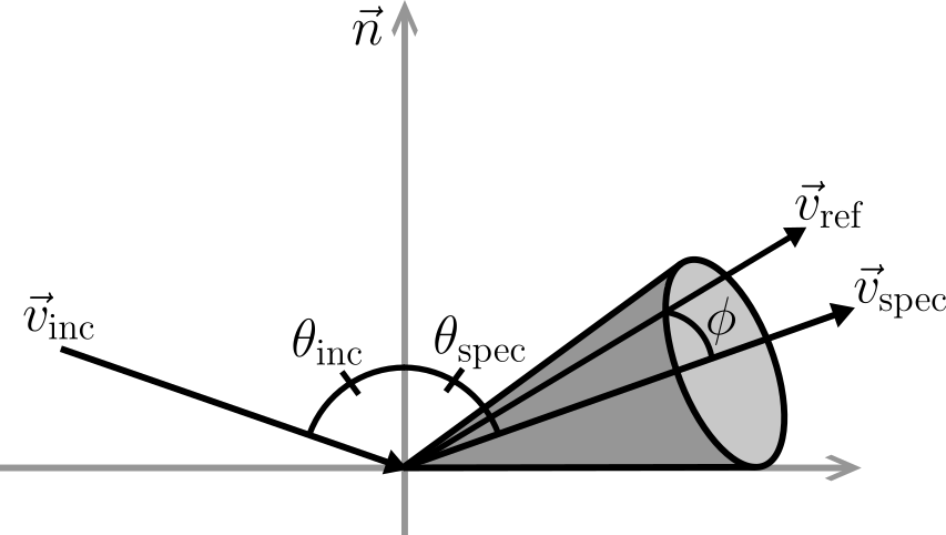
Ions striking the surface at an angle denoted by $\theta$ relative to the surface normal undergo reflection, where the angular dispersion is characterized by a cosine function centered around the direction of specular reflection defined by $\theta_\textrm{spec}$. This reflection process distinguishes between ions approaching the surface at glancing angles, which undergo nearly perfect specular reflection, and those striking the surface perpendicularly, which undergo nearly diffuse reflection.
\begin{equation} \mathrm{P}(\phi) \propto \cos \left(\frac{\pi}{2} \frac{\phi}{\frac{\pi}{2}-\theta_\textrm{spec}}\right) \quad \text{ if } \theta_\textrm{inc} \leqslant \theta_\textrm{min} \end{equation}
\begin{equation} \mathrm{P}(\phi) \propto \cos \left(\frac{\pi}{2} \frac{\phi}{\frac{\pi}{2}-\theta_\textrm{min}}\right) \quad \text{ if } \theta_{\textrm{inc}}>\theta_{\textrm{min}} \end{equation}
The ray’s reflected direction is randomly chosen from a cone around the specular direction. The opening angle of this cone is given by the incidence angle $\theta$.
The ions sticking probability is described by two parameters $\theta_\textrm{Rmin}$ and $\theta_\textrm{Rmax}$: \begin{equation} \beta_{ion} = 1 \quad \text{ if }\theta \leq \theta_\textrm{Rmin} \end{equation} \begin{equation} \beta_{ion} = 1 - \frac{\theta - \theta_\textrm{Rmin}}{\theta_\textrm{Rmax}- \theta_\textrm{Rmin}} \quad \text{ if }\theta > \theta_\textrm{Rmin} \end{equation}
Neutrals
There are two neutral particle species in this model: etchant (Flourine) and oxygen. The sticking probability is a function of the surface coverage and the sticking probability of the respective particle. The sticking probability is given by: \begin{equation} \beta_{eff_{F/O}} = \beta_{F/O} (1 - \theta_F - \theta_O) \end{equation} Neutrals reflect diffusely from the surface with a cosine distribution.
Implementation
Time and length units have to be set before initializing the model. For details see Units.
SF6O2Etching() // use default values only
SF6O2Etching(const double ionFlux, const double etchantFlux,
const double oxygenFlux, const NumericType meanEnergy /* eV */,
const NumericType sigmaEnergy /* eV */,
const NumericType ionExponent = 100.,
const NumericType oxySputterYield = 2.,
const NumericType etchStopDepth =
std::numeric_limits<NumericType>::lowest())
SF6O2Etching(const PlasmaEtchingParameters<NumericType> ¶meters)
// static function to get default parameters
static PlasmaEtchingParameters<NumericType> defaultParameters()
Users can access and modify all detailed parameters by creating a PlasmaEtchingParameters struct, which encapsulates the following relevant values:
All flux values are units 1015 / cm2 /s2.
| Parameter | Description | Default Value |
|---|---|---|
ionFlux | Ion flux | 12.0 |
etchantFlux | Etchant flux | 1800.0 |
passivationFlux | Oxygen flux | 100.0 |
beta_E | Sticking probability map for fluorine | 0.7 (on Si and Mask) |
beta_P | Sticking probability map for oxygen | 1.0 (on Si and Mask) |
etchStopDepth | Depth at which etching stops | -inf |
Mask.rho | Mask density (1022 atoms/cm³) | 500.0 |
Mask.Eth_sp | Mask sputtering threshold energy (eV) | 20.0 |
Mask.A_sp | Mask sputtering coefficient | 0.0139 |
Mask.B_sp | Mask sputtering coefficient | 9.3 |
Substrate.rho | Silicon density (1022 atoms/cm³) | 5.02 |
Substrate.Eth_sp | Silicon sputtering threshold energy (eV) | 20.0 |
Substrate.Eth_ie | Silicon ion enhanced etching threshold energy (eV) | 15.0 |
Substrate.A_sp | Silicon sputtering coefficient | 0.0337 |
Substrate.B_sp | Silicon sputtering coefficient | 9.3 |
Substrate.A_ie | Silicon ion enhanced etching coefficient | 7.0 |
Substrate.k_sigma | Silicon chemical etch rate coefficient (1015 /cm² /s) | 300. |
Substrate.beta_sigma | Silicon oxygen recombination coefficient (1015 /cm² /s) | 0.05 |
Passivation.Eth_ie | Passivation ion enhanced etching threshold energy (eV) | 10.0 |
Passivation.A_ie | Passivation ion enhanced etching coefficient | 3.0 |
Ions.meanEnergy | Mean ion energy (eV) | 100.0 |
Ions.sigmaEnergy | Standard deviation of ion energy (eV) | 10.0 |
Ions.exponent | Exponent of power cosine source distribution of initial ion directions | 500.0 |
Ions.inflectAngle | Inflection angle (rad) | 1.55334303 |
Ions.n_l | Exponent of reflection power | 10.0 |
Ions.minAngle | Minimum cone angle for ion reflection | 1.3962634 |
Ions.thetaRMin | Minimum angle for ion sticking probability | 70.0 (deg) |
Ions.thetaRMax | Maximum angle for ion sticking probability | 90.0 (deg) |
Example usage:
C++
// namespace viennaps
...
auto parameters = SF6O2Etching<NumericType, D>::defaultParameters();
parameters.ionFlux = 10.;
parameters.Mask.rho = 500.;

auto model = SmartPointer<SF6O2Etching<NumericType, D>>::New(parameters);
...
Python
...
parameters = vps.SF6O2Etching.defaultParameters()
parameters.ionFlux = 10.
parameters.Mask.rho = 500.

model = vps.SF6O2Etching(parameters)
...
Related Examples
-
Rodolfo Jun Belen, Sergi Gomez, Mark Kiehlbauch, David Cooperberg, Eray S. Aydil; Feature-scale model of Si etching in SF6 plasma and comparison with experiments. J. Vac. Sci. Technol. A 1 January 2005; 23 (1): 99–113. https://doi.org/10.1116/1.1830495 ↩ ↩2